
AI FOR HARDWARE DESIGN
AI for hardware design, from requirements to working hardware
AI for hardware design should not stop at a chat answer or a diagram that merely looks complete. IterXAI keeps requirements, finished-module facts, BOMs, firmware, connections, carrier boards, fabrication, and physical evidence inside one reviewable project.
For electronics and embedded prototype teams, robotics and IoT developers, teaching labs, and hardware startups—not a claim of one-click silicon RTL, mechanical CAD, or production engineering.
DIRECT ANSWER
What does AI for hardware design mean in practice?
AI for hardware design uses AI to turn product requirements into reviewable engineering artifacts: functions and I/O, finished-module choices, BOMs, firmware, connections, checks, and test evidence. IterXAI focuses on electronics, embedded firmware, carrier-board design, desktop PCB prototyping, and physical validation; it does not claim to replace specialist silicon RTL, mechanical CAD, safety review, or production engineering.
First, define which layer of hardware design you mean
The query spans silicon, electronics, firmware, mechanics, and manufacturing. A useful tool states its boundary before asking you to trust its output.
| Design layer | IterXAI fit | Role in this guide |
|---|---|---|
| Silicon and RTL | Adjacent | Use specialist EDA, HDL, and verification flows; this is not IterXAI's current product focus. |
| Electronics and PCB | Core | Structure functions and interfaces, finished modules, BOMs, connections, carrier boards, and pre-fabrication checks. |
| Embedded firmware | Core | Keep the target MCU, real pins, code, builds, simulation, and board facts aligned. |
| Mechanical and enclosure | Handoff | Retain dimensions, connectors, and assembly constraints for mechanical CAD and structural engineering. |
| Fabrication and physical test | Prototype loop | After human confirmation, continue into desktop PCB fabrication, assembly, power-on, and physical behavior. |
A six-step path from one requirement to working hardware
Every step produces an input the next step can inspect. AI accelerates preparation; people own electrical, safety, manufacturing, and product release decisions.
- 01
Define the goal and constraints
State the problem, operating environment, power source, and the evidence that would count as success.
Reviewable output: Requirements, environment, non-goals, acceptance criteria - 02
Break it into functions and interfaces
Identify inputs, outputs, communications, power, and risks before drawing a board that merely looks complete.
Reviewable output: Functional blocks, I/O, risks, open questions - 03
Choose finished modules and component facts
Prove behavior with mature core boards and finished modules first, then retain trusted pins, footprints, and substitution constraints.
Reviewable output: Module architecture, candidates, sources, constraints - 04
Align the BOM, connections, and firmware
Use one project to constrain purchasing, physical pins, connections, and program goals so they cannot drift independently.
Reviewable output: BOM, nets, pin map, firmware scaffold - 05
Validate builds, simulation, and rules separately
A successful build, simulated behavior, and electrical or fabrication checks are different evidence, not one green status.
Reviewable output: Build receipts, simulation results, issue list - 06
Fabricate and test after human confirmation
Confirm critical outputs, then fabricate, assemble, power on, and return physical findings to the next revision.
Reviewable output: PCB, assembly record, test evidence, revision input
First-hand evidence from the current product
These are published IterXAI software interfaces, the hardware AI workspace, and desktop fabrication equipment—not stock concept imagery. Open each item for its product context.
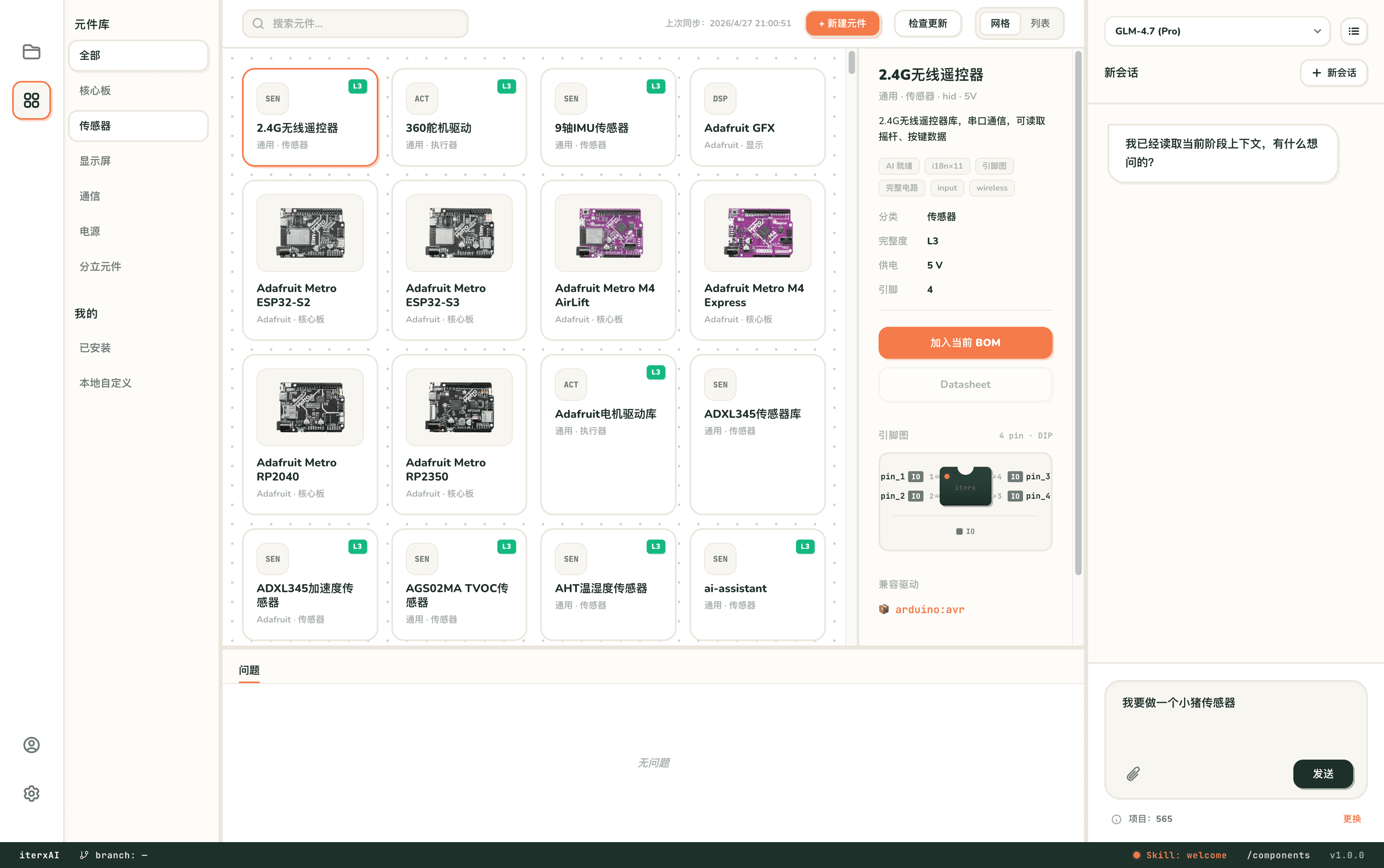
AI IDE: project context
Keep requirements, modules, firmware, and validation inside one hardware project.
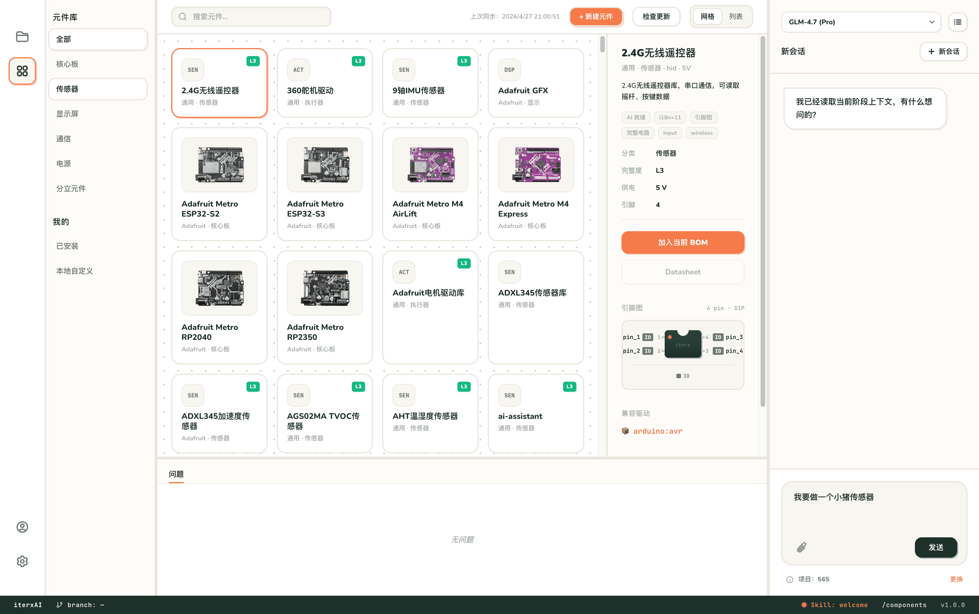
Hardware AI: facts and checks
Assist around modules, components, BOMs, connections, and explicit uncertainty.
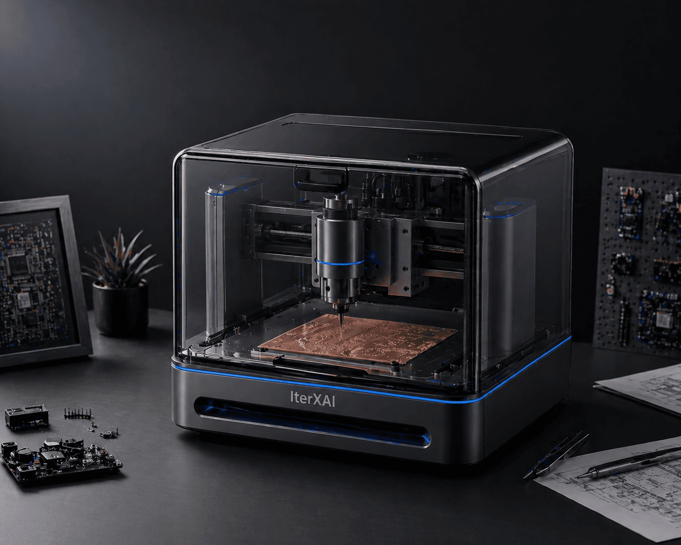
Desktop fabrication: physical feedback
Move a confirmed prototype board into on-site fabrication and real testing.
Different AI tools solve different breaks in the workflow
This is a boundary guide, not a brand leaderboard. General chat is useful for exploration, PCB assistants focus on board work, and IterXAI is designed to retain the context of the wider prototype loop.
| Decision point | General AI chat | PCB-focused assistant | IterXAI project flow |
|---|---|---|---|
| Primary context | Current conversation and pasted sources | Schematic, layout, and rules | Requirements, modules, BOM, firmware, carrier, and tests |
| Typical output | Explanations, draft plans, code fragments | Board advice and design files | Constrained project artifacts and validation evidence |
| Component facts | Depend on sources supplied by the user | Depend on the tool's libraries | Tied to project sources; unknowns stay explicit |
| Physical feedback | Usually outside scope | Usually ends at manufacturing handoff | Connects desktop prototypes, assembly, and physical tests |
| Human responsibility | Review the answer | Review circuits and fabrication outputs | Explicitly confirm critical gates before continuing |
Inspect the products and the complete physical flow
Use the product pages and full demonstration to decide whether this workflow fits your project.
Turn a requirement into an engineering contract
AI first separates the goal into functions, I/O, power, operating constraints, and validation criteria, then organizes the architecture around mature core boards and finished modules.
- Requirements and non-goals
- Functional blocks and I/O
- Finished modules first
- Explicit unknowns and confirmations
Keep BOMs, pins, firmware, and connections constrained
Component sources, physical pins, connections, and program goals cannot drift independently. One project ties them to real sources and execution receipts.
- Reviewable BOM
- Trusted pins and footprints
- Separate build and simulation evidence
- Connection and rule issue list
Make fabrication and testing inputs to the next design
People confirm critical outputs before fabrication, assembly, and power-on. Physical behavior and failure records return to the next revision instead of generated output becoming manufacturing truth.
- Human pre-fabrication gate
- Desktop PCB prototype
- Assembly and power-on record
- Physical evidence for revision
PHYSICAL OUTCOMES
A reviewable AI hardware design data flow
- 01Goals, constraints, and acceptance criteria
- 02Finished modules and component sources
- 03BOM, connections, and pin map
- 04Firmware builds and simulation receipts
- 05Carrier board and pre-fabrication checks
- 06Physical PCB, assembly, and test results
QUESTIONS
AI for hardware design questions
Does AI for hardware design include silicon RTL?
The query spans several layers, but IterXAI currently focuses on electronics, embedded firmware, carrier boards, PCB prototypes, and physical validation. Silicon RTL needs specialist HDL, EDA, and verification flows.
Does IterXAI make every engineering decision automatically?
No. AI organizes requirements, candidate architectures, BOMs, firmware, and checks; people confirm critical electrical, manufacturing, safety, and product decisions.
How do you keep AI hallucinations out of physical hardware?
Critical conclusions are tied to component sources, project files, and execution receipts. Unknowns remain explicit, while builds, simulation, fabrication, and physical tests are validated separately.
Can it turn one prompt directly into a production PCB?
That is not a responsible promise. It helps form and validate an electronics prototype; production still requires professional DFM, mechanical, certification, supply-chain, and production-test work.
START WITH ONE REAL PROBLEM
Test AI for hardware design on one real project
Describe the device, operating environment, power source, and physical test it must pass. We will begin from a verifiable engineering contract.
Book an AI IDE demo →